Final Project: Duck Lamp
Since Mr Rodney has expressed his extreme want on having a new table lamp for the soldering station, I have decided to go along his wishes and build one for my final project. (In hopes of getting higher marks >.<) The following are the steps that I took to complete my final project and I have broken it into different parts for ease of reading.
Research & Design
STEP 1: First of all, I have decided to do some research online through the Instructables website to get some inspiration. I got inspiration from a design on instructables by Darbin Orvar and I decided to recreate it but make some changes to the embedded programming.STEP 2: After getting some inspiration through my research, I have settled on a design and drew it out to see the design and see if there are any other extra changes that may be needed. This was my first rough sketch.
-1.jpg)
-2.jpg)
STEP 3: I have decided that my initial design was not as smart as I thought it was therefore I was contemplating if I should push the box back or if i should just move it to the back.
STEP 4: After comparing the pros and cons, I have decided that pushing the box back was a little dumb as the light would only be shining on the box and not at where the user would want to be. Hence my decision was to bring the box to the back and rotate it such that the buttons are on the side of the dominant hand of most people - the right hand. After coming up with a new design, I drew it out again. I then decided to do an actual prototype so that I can see if it was practical to use this design.
-1.jpg)
-2.jpg)
Link to Darbin Orvar's design: click here
Prototype
STEP 1: Firstly, I went around my house in search for some sturdy cardboard and I managed to find some as shown below..jpg)
STEP 2: Next, I started to measure and cut them out to the size that I see fit for the table lamp that I will be making. I also started to cut some holes in them to ensure that the cardboard could fit nicely and therefore create the effect of a lamp.
.jpg)
STEP 3: I then started to put the parts together and assemble my table lamp prototype.
.jpg)
-2.jpg)
STEP 4: I added some lines and circles in a black marker to indicate where I would be making any cuts or engraving.
.jpg)
-2.jpg)
-3.jpg)
-4.jpg)
STEP 5: After taking a look at my prototype, I felt like it could be improved as there was extra space at the front of the base that was designated for weights. However since I will be making a double layered base, I have decided to move the weights under the box instead of dedicating a space at the front of the base for it. This helps to save space needed on the table to place the table lamp as well as to ensure that the light will be shining wherever the user wants it to be shined at. I then transferred the design to Fusion 360 to have the design ready for laser cutting. After, I made any changes that I had to make to the design, on Fusion 360 and decided to just go ahead and laser cut the design out to see how it would balance using that material.
*Due to time constraints, I have decided to not do a 3D fusion 360 design. Instead I used Fusion 360 to do my designs in 2D, so that I can use the template to do the laser cutting.*
Laser Cutting
STEP 1: After saving my design, I converted the sketch into a dxf file and uploaded it into the laser cutting machine.STEP 2: After uploading my design into the laser cutting machine, the machine started to cut out the design that I have uploaded. The material used to cut the draft is cardboard since it is only a draft piece and not the actual final product. Below is the outcome.
.jpg)
-2.jpg)
STEP 3: Next, I started to put the parts together to assemble my draft table lamp. However, I have found out that there we some mismeasurements after trying to put it together. Thus, I would have to make changes to the measurements once again.
-1.jpg)
-2.jpg)
STEP 4: Since I had to make adjustments to my measurements, I used a ruler to measure the actual lengths and decided if I needed it to be shorter or longer. I made the readjustments on Fusion 360 and saved my design once again as a dxf file and uploaded it to the laser cutting machine and send it for cutting. STEP 5: After uploading my design into the laser cutting machine, the machine started to cut out the design that I have uploaded. The material used is the same as the earlier since it is also a draft piece and not the actual final product. Below is the outcome.
.jpg)
STEP 6: I have decided that I needed to do some additional adjustments to the design in fusion 360 as some parts were abit off. Thus, I went on to do the needed adjustments and finalised my deisgn. After finalising the design, I downloaded the design and uploaded it to the laser cutting machine and printed it on plywood this time since it was going to be my final product.
STEP 7: The first picture shows how it came out to be and the second shows the table lamp after it has been more or less assembled.
-1.jpg)
-2.jpg)
Fusion 360 design file for my final project: final project design.f3d
Fusion 360 design file for my final project the box: box design.f3d
3D Printing
STEP 1: Firstly, I used Fusion 360 to design the knob for the potentiometer to adjust the brightness of the light. I have decided to create a knob to make it easier for the user to use the potentiometer to adjust the brightness of the table lamp. I have decided to create the knob by using a cylinder to cut into the bigger cylinder.STEP 2: I used the function combine together with cut to create a new component which would be the knob. I then downloaded the design to upload it to the 3D printing machine.
.jpg)
STEP 3: This is the final look of the knob that I have 3D printed and this is how it looks like.
.jpg)
Fusion 360 design file the knob: knob design.f3d
Engineering
STEP 1: I approached Mr Rodney for components that I would need to construct my table lamp which includes things like: LED strips, a nano board, a potentiometer, a transistor, and so on..jpg)
STEP 2: Using the LED strips, I soldered 2 strips of 4 LEDs each, together with a single cord wire. After sticking the LED strips to the top part of the table lamp, I have decided to use a shrinking tube to keep the wires neat and tidy.
.jpg)
STEP 3: After, I tried to wire everything together on the breadboard which was connected to a nanoboard. Due to sizing constraints, I was unable to use the Arduino UNO board. After that, I started to produce the coding with a bit of help from the library on the website that Mr Rodney has made.
.jpg)
STEP 4: I decided to use a mini breadboard instead of the tiny breadboard that Mr Rodney had provided me along with the nanoboard as I needed to do alot of wiring thus the tiny breadboard would not have sufficed. I also made use of the transistor to get the potentiometer running and working. This is how the final wirings looked like on the nanoboard. Below is the code that I have used for the project.
.jpg)
View my code here: code
Putting it all together
STEP 1: I fit the individual wires into their respective holes in the lamp that was created for them. An example being the LED wires that were put through a shrinking tube, that was to be put through the hole at the top of the back piece, runs down the back piece and into the hole which leads to the box.STEP 2: After fitting the wires through, I started to join the seperate parts of the lamp together and knocked them into their respective holes. For example the sides of the box into the base.
STEP 3: I used some tape to secure some parts of the lamp like the wiring behind the back piece to ensure that the wires would not be hanging about and create a hazard to the user.
.jpg)
STEP 4: This is how the final product looks like.
.jpg)
Presentation
To prepare for the presentation, we were tasked to make a 1-minute video depicting our final product as well as a one-page slide to 'sell' our product.To view the video: watch the video here
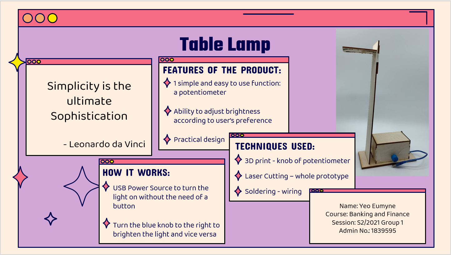
Presentation slide:
Click here to return the 'Assignments' page.